 MTI UK
  FWT
FWT
Developing and engineering a part for the aerospace industry is no easy task — but then again, why should it be? Companies depend on these parts to help keep passengers and cargo safe each time a plane takes off, lands and every step in between.
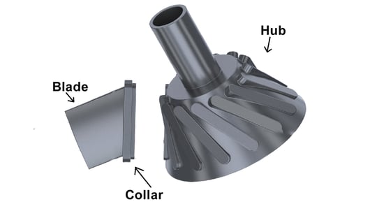
Among the hundreds of parts MTI friction welds for the aerospace industry, it's quite possible no other part is more complicated to join than the blisk.
We introduced you to blisks in past Whiteboard Wednesdays episodes. Short for bladed disk, blisks are typically made out of titanium and, in most cases, are located in the compressor section of an aircraft engine.
As we've explained previously, blisks are machined out of a single forging, but this method is not ideal because it's often expensive and time-consuming to do so.
Instead, MTI uses linear friction welding to forge each blade onto the hub as many as 20 separate times to make a full assembly.
Since we've already demonstrated how we join each blade to the hub, we want to dig deeper into the complexity of getting that weld right every time.
ACHIEVING TOLERANCE
Blisks, as useful and innovative as they are, aren't very forgiving. In fact, we're asked to hold 0.05 millimeters true position of a blade relative to the hub. To put that into perspective, that's a fraction of the diameter of a human hair.
While we talk about true position, we need to be able to hold the blade tolerance within six degrees of freedom, which include:
The direction of oscillation of the blade
The side-to-side motion of the blade
The rotational axis
Angular axes
IT'S ALL IN THE TOOLING
To help stay within such exact standards, we rely heavily on the tooling, which only needs to take up a fraction of the tolerance we need to achieve from the process standpoint.
In order to make a weld where we oscillate vertically and forge horizontally, we need to be able to open up the tooling after the weld is complete so the welded blade can remain on the hub.
That's a big task, both literally and figuratively, because the blades we're welding can be in a full diameter of four feet, with a high degree of twist.
To help accomplish this, we utilize a two-piece tool. We can open it, insert a new blade then extract the old one with relative ease.
It's crucial that the tool is able to hold on to the collar datums, which have very tight tolerances. We ultimately need to ensure that the datums on the tooling are hitting the datums on the part.
As the oscillation occurs, we need to prevent part movement that would cause tooling wear, which causes a low tooling life and can impede our efforts of achieving tight tolerances.
Similarly, we need to be able to apply enough clamp force to keep the blade stationary so when we oscillate, the tool doesn't open and close with the process forces that we may experience. This will ensure the tool is not deflecting in an opening, upward or downward direction, while trying to minimize the amount of mass we use.
At the end of the design phase, we machine out the tooling like a piece of Swiss cheese in order to minimize the mass so we can maximize the machine performance.
Those are some of the difficult tooling challenges we need to overcome on the blade side.
But we're only getting started.
SWITCHING SIDES
Now, let's focus on the hub side of the tooling.
First, let's focus on the part itself.
In this application, we're dealing with a compound angle, which is a combination of the stagger angle of the blade and the hade angle of the disc. We need to neutralize both of those angles so that we can oscillate in an up and down motion, while ensuring everything is square to each other.
Once we make one weld, we need to be able to index around to the next weld location. This indexing motion is very precise — within a few arc seconds — so we can end up in a spot that does not compromise the tolerance we need to achieve.
After the motion, we need to verify that the blade tool and the hub tool are aligned to each other.
Remember, the process forces involve 80,000 pounds of friction force with 150,000 pounds of forge force — that's why we need to make sure we're not getting tool deflection on the hub side, either.
It's also important to note that any machine deflection we see as a result of the process forces will also impact our tolerance. Our tooling all sits on bed of machine. The machine itself can't deflect so we have to design the machine frame to be able to accept the tooling and withstand the process forces without deflection.
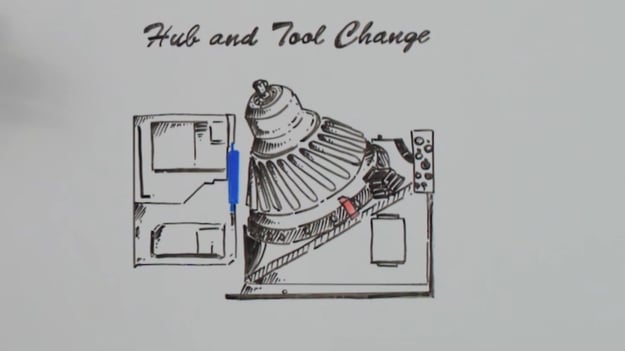
Lastly, when we move from welding one blisk to another blisk , we need to be able to repeatedly change the tooling in a way that we don't have a tolerance associated with the tool change.
While there is a lot of engineering that goes into the linear friction welding of blisks, these are some of the major tooling challenges we face. Fortunately, MTI has a proven record of friction welding blisks so we know how to overcome even the trickiest of applications.
Our LF35-75 has the largest tooling envelope of any linear friction welder in the world and is ideal for blisks. Contact us today to begin your development work at the LIFT facility in Detroit, Michigan.