If you asked 10 of our customers what friction welding looks like to them, chances are, they’d all have different answers.
To some, it’s a solid-state method used to join parts that can fit in your pocket. And to others, it’s the only technology suitable for joining parts complex and large enough to help an engine lift a jet off the ground. Most other answers, though, would likely fall somewhere in between those two scenarios.
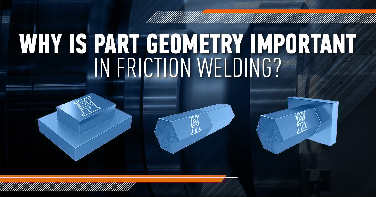
With such broad and diverse capabilities, it’s really no surprise that friction welding comes in a lot of different shapes and sizes. In this blog, we will explore the importance of part geometry in friction welding and explain how it can make the difference between a good part and a great part.
DETERMINING THE RIGHT FIT
When you have your first discussion with an MTI sales engineer, it won’t take long for weld geometry to enter the conversation. In fact, it’s one of the three primary factors we use to determine the amount of energy and forge load required to make a good weld:
- Area of the weld interface
- Materials being joined
- Weld interface geometry
If you aren’t yet sure which geometry is best for your part — don’t worry. MTI has an entire team of experienced engineers to help research and answer that question for you.
Weld geometry is typically driven by three key factors, which an MTI sales engineer will also discuss with you:
- Finished part geometry
- The materials being welded
- Performance requirements of the finished part
MTI can consult you on the design of a weld interface that will meet the performance requirements of the part, while minimizing pre and post-weld processing.
Next, let’s explore some possible geometries to give you an idea of the scope of possibilities in this highly customizable technology.
CHOOSING THE RIGHT GEOMETRY
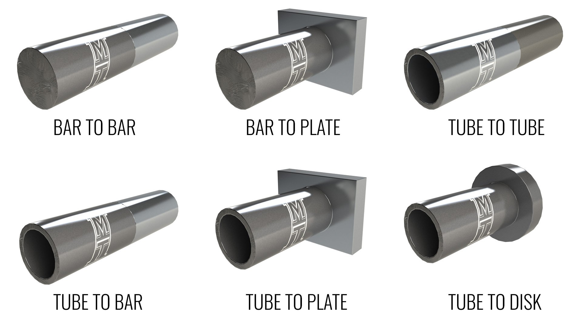
For the purpose of this blog, we will primarily focus on six different weld geometries most frequently considered for rotary friction welding applications. Almost all rotary friction welds are butt joints using one of the following six geometries:
- Bar to bar
- Bar to plate (requires approximately 20 percent more energy, 10 percent more load)
- Tube to tube
- Tube to bar (requires approximately 10 percent more energy, five percent more load)
- Tube to plate (requires approximately 20 percent more energy, 10 percent more load)
- Tube to disk (requires approximately 10 percent more energy, five percent more load)
While it is possible more than one geometry could work for an application, it ultimately depends on the materials being welded and how the part is going to be used. In general, a bar to bar or tube to tube design offers the most desirable results.
Tubular interface geometries require less energy and load than solid interface welds. This is because upset material can move to both the inner diameter (ID) and outer diameter (OD) of a tube, instead of only to the OD.
In addition, tubular welds provide a greater degree of latitude than welds involving solid materials (such as bars) because center heating is not a factor.
Other factors we use to determine the best weld geometry for your application include:
- Eliminating a metallurgical notch in critical stress areas
- Hardness in the weld zone
- Whether flash removal is needed
ANOTHER FACTOR TO CONSIDER
One of the key benefits of friction welding is the ability to join dissimilar metals. In some cases, utilizing bimetallics could become a factor when evaluating weld geometry. For example, bar to plate or tube to plate geometries will dissipate heat away from the weld interface faster than a bar to bar geometry. This could be a factor if one of the materials is a high-temperature alloy or has high hardenability properties.
OPTIMIZING YOUR APPLICATION
Once we have determined the best route forward for your part, we will enter the weld development process. In this stage, we are able to test out your materials and application in our in-house metallurgical lab and friction welders to ensure optimal strength and performance requirements.
If a part does not meet expectations during weld development, we will modify weld parameters to achieve a stronger result. If more improvements are needed, we will take another look at the weld interface geometry.
By the time the weld development process is complete, we will have successfully identified whether your materials and part geometry can work together to produce a part to exceed your expectations.
LET’S GET STARTED
While this blog has covered many of the main points associated with weld geometry and friction welding, there are still a lot more avenues to discover and levers to pull. Even though this blog focused on rotary geometries, there are also several different linear geometries that impact a final part as well. Many of these factors are also used when considering Low Force Friction Welding, which is our newest solid-state joining technology.
To start a conversation specific to your application, contact us today to get connected to one of our sales engineers!