 MTI UK
  FWT
FWT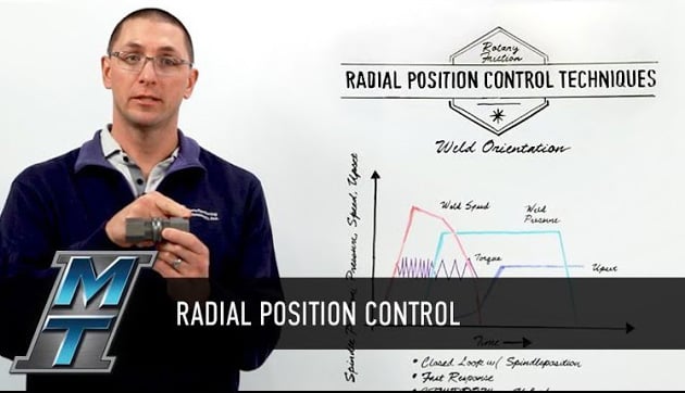
It's no secret Friction Welding is a highly scientific process; it involves a lot of calculations, engineering and research to get it right. But thanks to the MTI-engineered control system found on each of our friction welding machines, you can trust our technology to do the complex work for you on your shop floor!
This week, we're talking about Radial Position Control or Weld Orientation. When we friction-weld two parts together on a machine, we need to ensure those parts are joined with radially location relative to one another. This is especially true for parts with complex geometries.
For example:

Look at the image above -- it represents a part with complex geometries that need orientation.
This part required us to weld together two hexagon-shaped flats. In this case, we needed to make sure the sides on hexagon #1 were aligned with hexagon #2.
There is very little room for error in this process; our customers usually want the orientation controlled within a half-degree of the full 360-degree spindle rotation. If the oriented features don't match within a half-degree once the spindle stops spinning and the weld is complete, the geometry of the welded component could be compromised.
So how do our friction welding machines get it right every time?
Let's imagine we are running an inertia weld.
STEP ONE: GETTING STARTED
First, the machine will create a profile of the spindle position, relative to time, from the start of the weld to the end of the weld. It will then use that profile as a baseline to generate an error signal for future welds.
Based upon the profile weld, we know where we need to stop and the control system will do the math for us to tell us where we need to start.
Any incoming part variations will prompt any needed adjustments, which are made with drive torque, to achieve the final position.
STEP TWO: CLOSE IT UP
The controls system on a friction welder is programmed to use torque to close the loop on spindle position. It will add torque to catch up with a spindle position that may be lagging behind or it will use negative torque (braking) to slow down the spindle position relative to the profile.
This highly engineered process creates a very responsive system for all types of applications. Run after run, the machine will make all needed adjustments to ensure the first friction-welded part in a batch looks and functions exactly like the last one.
MTI CAN SOLVE YOUR PROBLEMS
Our expert engineers have a deep understanding of friction welding processes and the wide variety of materials that can be used. With our knowledge and equipment, we know how to achieve the maximum utilization of each material to ensure you get the highest quality parts that are perfectly catered to your applications. We’ll build a machine that makes your part, we’ll make the part for you, or we’ll help you make the part even better. Contact us to get started.